USB-C done cheap: when 2 ports become 1
February 29, 2020
I’ve recently upgraded my main computer to an AMD Ryzen-based setup, with the ASUS TUF B450-Plus Gaming motherboard. Unlike the Gigabyte motherboard on my previous Intel Skylake-based setup, this one has an USB Type-C port. It’s a good motherboard for its price point, but one thing in the spec sheet struck me as odd (quite literally): it has a total of 13 USB ports, split between 6 on internal headers, 6 USB-A and a single USB-C; whereas the Ryzen SoC and B450 chipset provide a combined total of 14 ports. Motherboards very often tap into all USB ports that their platform provides, with high-end ones going as far as adding external USB controllers, so why does this one happen to be one port short? Did they run out of room or budget to add one more connector?
The answer is simple: that single USB-C port consists of two USB ports masquerading as one.
USB-C implementation
USB-C is a complex beast. The connector’s mirrored, orientation-agnostic design, as well as its ability to carry more than just USB data, add to the complexity of implementing it on a device. There’s also the matter of USB-C connectors costing more than Micro-USB connectors - a chicken-and-egg problem where Micro-USB is such a common part that prices are driven to rock bottom - which is why you don’t see it being used everywhere just yet.
In order to cut down on the aforementioned complexity for simpler USB 2.0-only devices, the USB-C specification1 allows female receptacles to common/short the USB 2.0 differential pair - the D+ and D- pins - across both orientations (table 3-4 footnote 1 and table 3-5 footnote 2), eliminating the requirement for orientation detection circuitry and signal muxes on such devices. However, the SuperSpeed pairs used for USB 3.x data are designed to be on fixed locations and cannot be commoned together due to stricter signal integrity requirements, necessitating the use of a signal switch/mux, even if the port only supports single-lane modes such as USB 3.x Gen1 or Gen2 (section 4.5.1.1). In this post, I’ll tell you all about one way manufacturers are skirting this requirement.
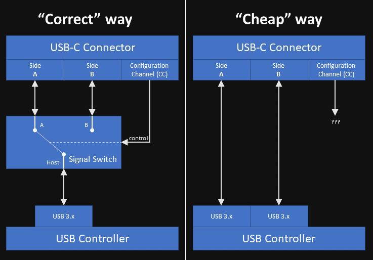
The “correct” way to go about implementing a single-lane USB-C port - outlined in Figure 4-4 as well as the diagram above - is by using a mux, which probes the Configuration Channel (CC) pins to determine the plug’s orientation and activate the correct SuperSpeed lanes on the receptacle. From a consumer electronics manufacturing standpoint of “a penny saved is a penny earned”, such muxes are expensive - let’s look into a few parts specified for USB 3.x Gen1, and how much they cost in quantity at retail (manufacturers obviously pay less than this) as of writing:
- The TI HD3SS3202 is a generic differential mux also rated for USB-C operation (datasheet sections 9.2.1 and 9.3.1) costing $0.61, which also requires an external CC controller such as the TPS25821 ($0.35) to determine the cable’s orientation.
- The TI TUSB542 is an all-in-one mux, redriver and CC controller, costing $1.85.
- The Pericom PI3USB302-A is another mux which requires an external CC controller such as the PI5USB30216C. Diodes/Pericom does not disclose direct prices on their website, but these parts have similar unit prices to their TI counterparts on retailers such as Mouser and Digi-Key.
- An honorable mention to the VIA Labs VL160, another all-in-one mux. I could not find it on any retailers (LCSC carries some of their parts but not this one), but from what I can guess - I’m just a software guy who has never done electronics for a living, let alone IC negotiation - these Eastern manufacturers tend to offer more affordable solutions overall.
The “cheap” way I suspect my motherboard is using takes advantage of the fact USB 3.x Gen1 only uses one of the two SuperSpeed lanes present on the USB-C connector, and unlike Gen2, it often does not require a redriver to improve signal integrity. This mux-free “hack” entails using two discrete logical USB ports for a single USB-C connector, by wiring one port to one side/orientation of the connector and another port to the other. A downside to this configuration is that Alt Modes such as DisplayPort cannot be supported, but these are rarely ever implemented on lower-end hardware.
Testing this theory
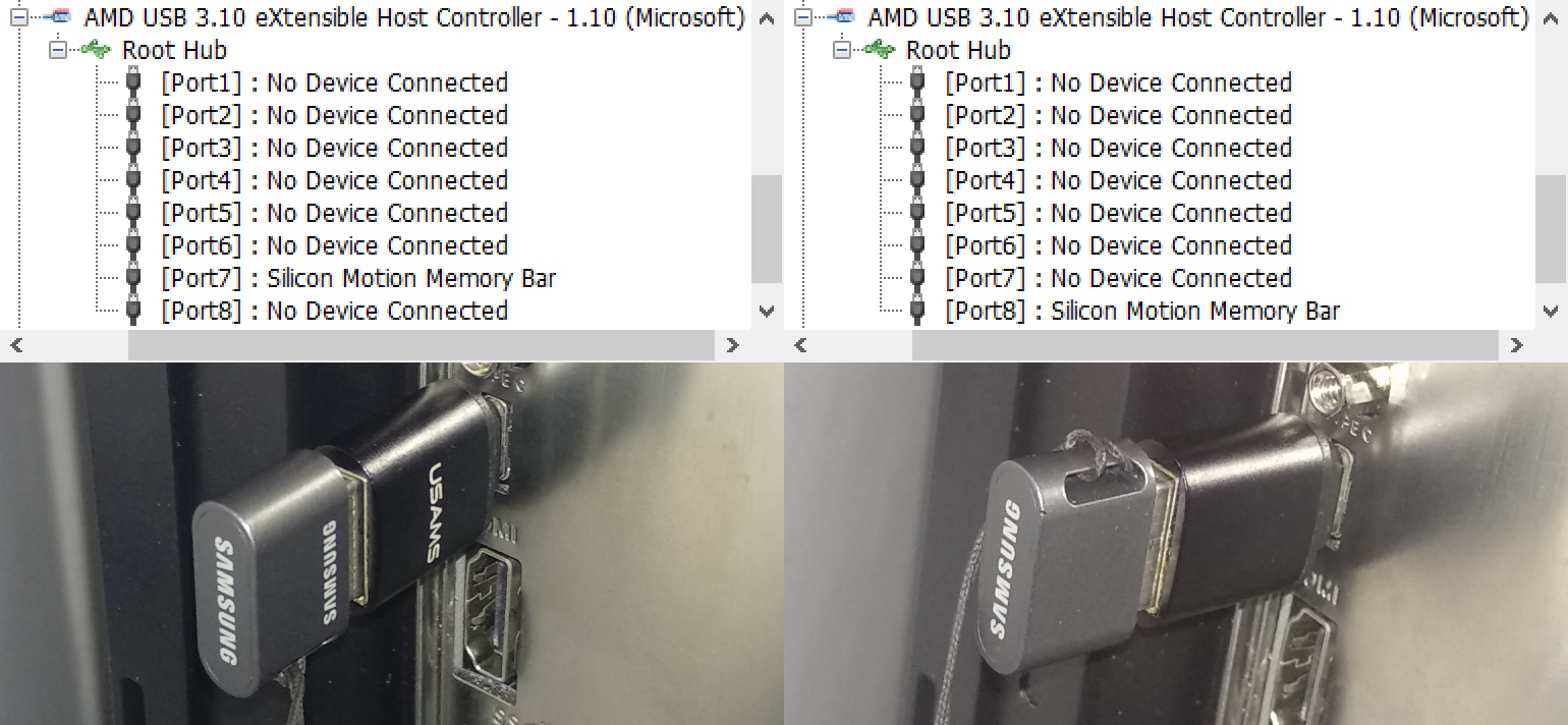
The easiest way to check if this holds true for a given computer’s USB-C port is by obtaining an USB-C device which supports USB 3.x Gen1 or Gen2 (but not Gen2x2 or USB 2.0), using an utility such as HWiNFO to check which logical port of the USB controller the device ends up being connected to, changing the device’s orientation, and using the utility again2 to check if the device is on a different logical port. The port also cannot support Alt Modes, as mentioned above.
The device I’m using for this test is a Gen1 flash drive attached to an USB-C to USB-A adapter. The picture below shows one orientation results in the flash drive being connected to logical port 7, and another orientation results in it being connected to logical port 8. I’ve also repeated this test with an USB 2.0 flash drive, and it always appears on logical port 3 regardless of the adapter’s orientation, indicating that the D+ and D- pins are commoned across both sides of the connector as allowed by the specification. This USB controller happens to be the one built into the Ryzen CPU, with 4 physical USB 3.x ports3 and therefore 4 logical USB 2.0 ports + 4 logical USB 3.x ports4; if I were to guess, the lower 4 ports displayed in HWiNFO correspond to USB 2.0 and the upper 4 correspond to USB 3.x, which makes port 3 the USB 2.0 counterpart to port 7, leaving port 4 unused.
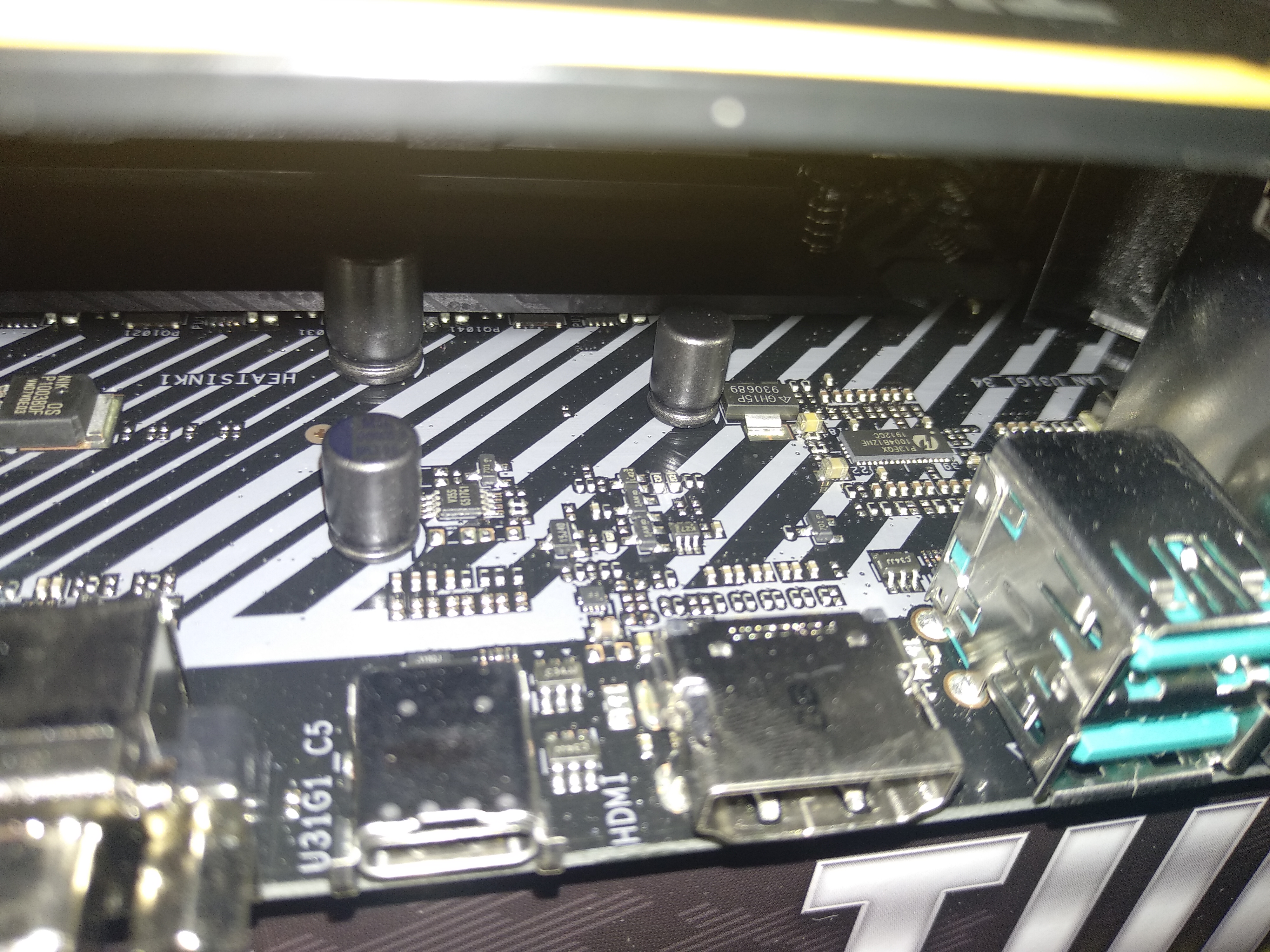
Let’s have a look at the motherboard itself. There are no large mux-like components located behind the USB-C connector, further proving the point that the engineers at ASUS wired two ports into a single connector in order to save a buck or two on the bill of materials. The Pericom PI3EQX1004B1 chip is a redriver for the pair of USB-A Gen2 ports off to the right.
The largest active component in the area is the unidentified 8-pin “V35S”, which is probably an USB power switch of some kind, judging by its proximity to a large capacitor. The motherboard surprisingly does comply with Section 2.3.1 by only powering the VBUS pins once a device connection is detected through the CC pins, tested by plugging the USB-C end of an USB-A to USB-C cable to the port and measuring VBUS on the USB-A end; there’s also a BIOS option to toggle power to the port.
As for power delivery, my Xiaomi Mi A1 phone charges from the port (with a 3 A USB-C to USB-C cable) at the default current of 500 mA, which indicates the port has its CC termination configured as Default USB Power (Rd = 5.1 kΩ), or the phone does not support USB-C power negotiation (requiring legacy USB Battery Charging negotiation instead), or both. 2021 update: I now have a Samsung Galaxy A72, which supports both USB-C power negotiation and USB Power Delivery; with the same 3 A USB-C cable, it successfully negotiates 5 V @ 3 A fast charging with the port.
Technically against the specification?
Section 4.5.1.1 states that the use of a switch/mux is mandatory for single-lane modes:
In the case of USB 3.2 SuperSpeed USB or USB4 TX/RX signals in a single-lane implementation, [the plug] requires the functional equivalent of a switch in both the host and device to appropriately route the TX and RX signal pairs to the connected path through the cable.
Right after Figure 4-4, the same section delegates the specific details on signal routing to the USB 3.x specifications:
The functional requirements for implementing TX/RX data bus routing for the USB Type-C receptacle are not included in the scope of this specification.
However, the USB 3.0 and 3.1 specifications predate USB-C and make no mention of it, and the USB 3.2 specification delegates the mechanical portion to the USB-C specification as well as a separate document for legacy connectors, while the electrical portion makes no mention of whether or not wiring different logical ports - not the same logical port as used by Gen2x2 - to each lane of an USB-C connector is a valid practice. If we take the USB-C specification’s word for it, it’s technically not valid due to the lack of a mux.
Other products doing this
AliExpress and eBay are full of inexpensive products which implement USB-C the way outlined in this post. You can easily tell them by the lack of components behind the USB-C port and the weird overall amount of USB ports. Here are a few I could find:
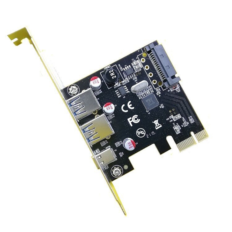
As for motherboards, the ASUS Prime B450-Plus is a plain version of my model - which I would have taken instead but no store had it in stock - with the same PCB layout and therefore the same “cheap” USB-C port. The Intel-based TUF B360-Pro Gaming has a similar layout as well. At the moment, I’m not aware of any models by other manufacturers with a single USB-C port standing out.
Should you feel cheated?
Not really. Despite this being a cost-saving measure, it is very clever, and allows USB-C to spread on to more hardware at the lower end.
Making a passive adapter to break out each of the two individual ports is technically possible but impractical, as it would essentially be an “USB hub with extra steps” with regards to its footprint and cost. An active hub controller would be required for handling USB 2.0 communication, as the USB 2.0 portion of the connector is often commoned together instead of being wired to the separate logical ports; at this point you technically have an USB hub. User experience is another issue, since non-technical users would expect the adapter to behave like a hub when it’s not one, failing the duck test, just like those passive A/V adapter cables which people expect to do signal conversion when they’re just passive breakouts made for some specific device.
-
All references on this post are valid for Revision 2.0 (August 2019). Further revisions may invalidate the references. ↩
-
HWiNFO does not rescan USB devices automatically, so make sure to restart it after reconnecting the device. ↩
-
The information AMD has released to the press isn’t entirely clear on what USB 3.x generation is supported by the Ryzen 3000 USB controller; they haven’t released any kind of I/O documentation for the AM4 platform. All CPU-provided ports on my motherboard are Gen1 only. ↩
-
USB 2.0 and 3.x have independent physical layers, therefore one physical USB 3.x port maps to two different logical ports in software. ↩